
在第二章第二节,我们就Analog Read Serial例子已经进行了详细讲述,内容包括原版教程的引用和翻译,实物连接图和原理图,程序的详细介绍等。下面我们不再包含英文教程和对应翻译,仅就各个范例的关键知识点进行讲述。
属于Basics类的示例项目包含如下6个:
* [Analog Read Serial](https://www.arduino.cc/en/Tutorial/AnalogReadSerial): 第二章我们已经详细介绍了这个例子(读取一个电位器的分压电阻的电压,将电压模数转换后通过串口发给pc机。
* [Bare Minimum](https://www.arduino.cc/en/Tutorial/BareMinimum): 这个例子仅仅展示了利用Arduino开发框架需要的基本结构,并没有实际功能。大家牢记:Arduino开发,框架要求我们完成两个函数:setup函数和loop函数,前者完成项目的初始化工作,只在开始执行一次;后者在Arduino工作其间,被循环调用,是真正完成各种工作的核心。
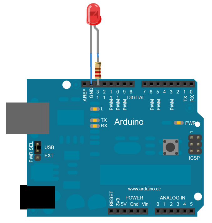
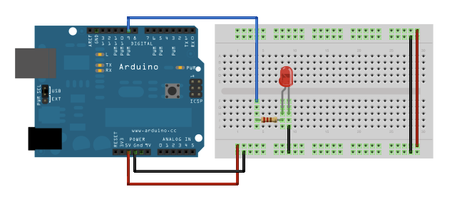
* [Blink](https://www.arduino.cc/en/Tutorial/Blink): 控制了Arduino开发板自带的Led灯的开关造成眨眼的效果。
:-: 
:-: 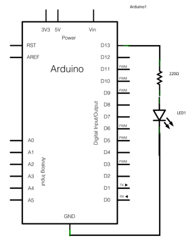
LED灯术语成为发光二极管,通过Arduino数字输出端口(高电平点亮,低电平熄灭)进行开关控制。必须和LED串联一个电阻(220欧姆)称之为限流电阻,降低Arduino输出功率,保护Arduino和Led。当然电阻值越大亮度越低,一般电阻值最大可以到1K欧姆,再大亮度就很低了。
```
// the setup function runs once when you press reset or power the board
void setup() {
// initialize digital pin LED_BUILTIN as an output.
pinMode(LED_BUILTIN, OUTPUT);
}
// the loop function runs over and over again forever
void loop() {
digitalWrite(LED_BUILTIN, HIGH); // turn the LED on (HIGH is the voltage level)
delay(1000); // wait for a second
digitalWrite(LED_BUILTIN, LOW); // turn the LED off by making the voltage LOW
delay(1000); // wait for a second
}
```
初始化setup函数里,设置LED-BUILTIN为输出模式。循环函数loop里不停设置该端口为高电平,调用延时,在设置为低电平,再次调用延时。不调用延时,大家的眼睛根本反应不过来。函数的概念和程序中void的含义,建议以后大家学习C语言的相应教程。目前不会影响大家对程序功能的理解。**LED_BUILTIN和HIGH,LOW都是Arduino内部预先宏定义,含义很好理解。
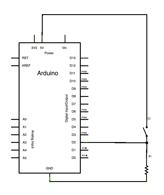
* [Digital Read Serial](https://www.arduino.cc/en/Tutorial/DigitalReadSerial): 读取了一个开关,将其状态通过Arduino串口监视器显示。
:-: 
:-: 
```
// digital pin 2 has a pushbutton attached to it. Give it a name:
int pushButton = 2;
// the setup routine runs once when you press reset:
void setup() {
// initialize serial communication at 9600 bits per second:
Serial.begin(9600);
// make the pushbutton's pin an input:
pinMode(pushButton, INPUT);
}
// the loop routine runs over and over again forever:
void loop() {
// read the input pin:
int buttonState = digitalRead(pushButton);
// print out the state of the button:
Serial.println(buttonState);
delay(1); // delay in between reads for stability
}
```
D2端口作为数字化输入在初始化setup进行功能定义,同时设定串口波特率。开关的作用使得D2和5V相连(闭合),打开则通过R1(10k欧姆)连接到地。R1被称为上拉电阻,隔离了电压和地(否则5v和地直连短路)。这种开关经常在Arduino中作为用户输入用,往往使用不止一个。其中的delay(1)可以减少干扰。当我们改变开关状态时,往往有一个不稳定的过渡状态,延时可以避免在过渡态进行输入,得到准确的结果。
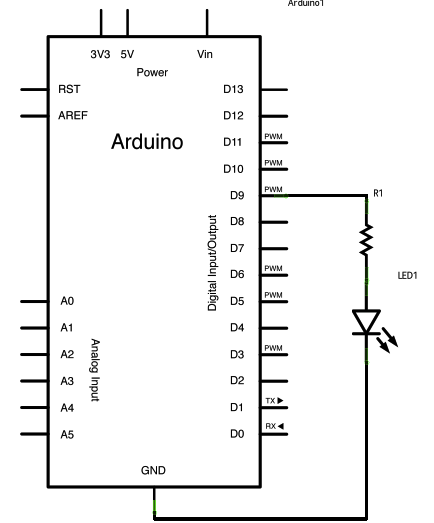
* [Fade](https://www.arduino.cc/en/Tutorial/Fade): 演示通过模拟输出控制LED的亮度逐渐改变。
:-: 
:-: 
```
/*
Fade
This example shows how to fade an LED on pin 9 using the analogWrite()
function.
The analogWrite() function uses PWM, so if you want to change the pin you're
using, be sure to use another PWM capable pin. On most Arduino, the PWM pins
are identified with a "~" sign, like ~3, ~5, ~6, ~9, ~10 and ~11.
This example code is in the public domain.
http://www.arduino.cc/en/Tutorial/Fade
*/
int led = 9; // the PWM pin the LED is attached to
int brightness = 0; // how bright the LED is
int fadeAmount = 5; // how many points to fade the LED by
// the setup routine runs once when you press reset:
void setup() {
// declare pin 9 to be an output:
pinMode(led, OUTPUT);
}
// the loop routine runs over and over again forever:
void loop() {
// set the brightness of pin 9:
analogWrite(led, brightness);
// change the brightness for next time through the loop:
brightness = brightness + fadeAmount;
// reverse the direction of the fading at the ends of the fade:
if (brightness <= 0 || brightness >= 255) {
fadeAmount = -fadeAmount;
}
// wait for 30 milliseconds to see the dimming effect
delay(30);
}
```
和上面例子不同的是通过PWM端口输出信号。
PWM信号是英文Pulse Width Modulation的缩写,不同占空比的PWM信号可以模拟不同的电压信号。好学的同学一定追问这个到底是怎么回事?详细解释可以看[https://www.arduino.cc/en/Tutorial/SecretsOfArduinoPWM](https://www.arduino.cc/en/Tutorial/SecretsOfArduinoPWM),也可以参考中文资料[https://blog.csdn.net/m0\_37738838/article/details/86630592](https://blog.csdn.net/m0_37738838/article/details/86630592)。
* [Read Analog Voltage](https://www.arduino.cc/en/Tutorial/ReadAnalogVoltage): 读取了模拟输入,在串口监视器显示电压值。
这个例子和Analog Read Serial基本一样,唯一的区别就在于电压值被转换为浮点数(数模转换将0~5 V的电压转换为0~1023的整数),该浮点数的范围是0~5,通过转换最终显示结果和电压真实值一致。就不在赘述了。仿真还是使用我们的tinkercad.com网站,文字不在描述,请参看对应视频教程里面。
- 序言
- 第一章 arduino简介和学习
- 第一节 arduino介绍
- 第二节 学习方法概述
- 第三节 计算机的智能
- 第二章 开始学习之旅
- 第一节 安装环境和购买硬件的说明
- 第二节 介绍一个具体的范例
- 第三章 分类官网教程讲解
- 第一节 Basics类的示例项目
- 第二节 数字端口的示例
- 第三节 模拟端口的示例
- 第四节 串口通信的示例
- 第五节 LED显示的示例
- 第六节 arduino处理矩阵键盘
- 第七节 LCD显示范例
- 第四章 综合实践项目制作教程
- 第一节 简单的计算器
- 第五章 复习题
- 单选题
- 编程题目
- 单选题答案
- 编程题答案
- 第1题
- 第2题
- 第3题
- 第4题
- 第5题
- 第6题
- 第7题
- 第8题
- 第9题
- 第10题
- 第11题
- 第12题
- 第13题
- 第14题
- 第15题
- 第16题
- 第17题
- 复习题包含翻译
- 第六章 快速复习
- 第一节 英文解说