
* [Blink Without Delay](https://www.arduino.cc/en/Tutorial/BlinkWithoutDelay): LED 闪烁而不使用 delay() 函数。
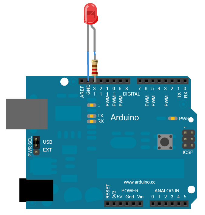
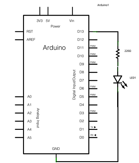
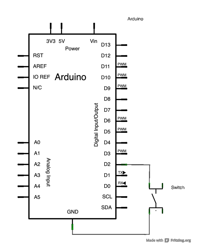
在Basics中有一个LED闪烁的项目,其中为了让大家看清闪烁在亮灭间使用了延时函数。使用延时函数时,Arduino一直等待,术语为计算机输入阻塞,无法读取用户输入信息。实际上计算机(也包括arduino)需要随时检测用户输入,因此这个例子就演示了保证输入响应下如何闪烁。硬件和blink连接完全一样:
:-: 
:-: 
```
// constants won't change. Used here to set a pin number:
const int ledPin = LED_BUILTIN;// the number of the LED pin
// Variables will change:
int ledState = LOW; // ledState used to set the LED
// Generally, you should use "unsigned long" for variables that hold time
// The value will quickly become too large for an int to store
unsigned long previousMillis = 0; // will store last time LED was updated
// constants won't change:
const long interval = 1000; // interval at which to blink (milliseconds)
void setup() {
// set the digital pin as output:
pinMode(ledPin, OUTPUT);
}
void loop() {
// here is where you'd put code that needs to be running all the time.
// check to see if it's time to blink the LED; that is, if the difference
// between the current time and last time you blinked the LED is bigger than
// the interval at which you want to blink the LED.
unsigned long currentMillis = millis();
if (currentMillis - previousMillis >= interval) {
// save the last time you blinked the LED
previousMillis = currentMillis;
// if the LED is off turn it on and vice-versa:
if (ledState == LOW) {
ledState = HIGH;
} else {
ledState = LOW;
}
// set the LED with the ledState of the variable:
digitalWrite(ledPin, ledState);
}
}
```
关键知识点就是使用 millis()函数循环中读取Arduino运行时间,然后计算和以前运行时间的间隔(通过减法实现),如果大于设定值,则改变LED的状态,并记录这时候的时间为以前运行时间。以前运行时间在setup中被设置为0。大家可以查阅该函数[https://www.arduino.cc/reference/en/language/functions/time/millis/](https://www.arduino.cc/reference/en/language/functions/time/millis/),此函数用于返回Arduino板开始运行当前程序时的毫秒数。这个数字在大约50天后溢出,即回到零。
这个程序不能显示出比调用delay函数带来的优势,因此结合键盘我们重新写了两端程序:
```
// constants won't change. They're used here to set pin numbers:
const int buttonPin = 2; // the number of the pushbutton pin
const int ledPin = 13; // the number of the LED pin
// variables will change:
int buttonState = 0; // variable for reading the pushbutton status
int lastbuttonState=0;
int keyPressNumber=0;
void setup() {
// initialize the LED pin as an output:
pinMode(ledPin, OUTPUT);
// initialize the pushbutton pin as an input:
pinMode(buttonPin, INPUT);
// initialize serial communication at 9600 bits per second:
Serial.begin(9600);
}
void loop() {
// read the state of the pushbutton value:
buttonState = digitalRead(buttonPin);
if(buttonState!=lastbuttonState)
{
lastbuttonState=buttonState;
keyPressNumber++;
// print out the state of the button:
Serial.println(keyPressNumber);
if(keyPressNumber>=10)
{
keyPressNumber=0;
}
}
digitalWrite(ledPin, HIGH); // turn the LED on (HIGH is the voltage level)
delay(1000); // wait for a second
digitalWrite(ledPin, LOW); // turn the LED off by making the voltage LOW
delay(1000); // wait for a second
}
```
另外一段程序如下:
```
// constants won't change. Used here to set a pin number :
const int ledPin = LED_BUILTIN;// the number of the LED pin
const int buttonPin = 2;
// Variables will change :
int ledState = LOW; // ledState used to set the LED
// Generally, you should use "unsigned long" for variables that hold time
// The value will quickly become too large for an int to store
unsigned long previousMillis = 0; // will store last time LED was updated
int buttonState = 0; // variable for reading the pushbutton status
int lastbuttonState=0;
int keyPressNumber=0;
// constants won't change :
const long interval = 1000; // interval at which to blink (milliseconds)
void setup() {
// set the digital pin as output:
pinMode(ledPin, OUTPUT);
// initialize the pushbutton pin as an input:
pinMode(buttonPin, INPUT);
// initialize serial communication at 9600 bits per second:
Serial.begin(9600);
}
void loop() {
// here is where you'd put code that needs to be running all the time.
// check to see if it's time to blink the LED; that is, if the
// difference between the current time and last time you blinked
// the LED is bigger than the interval at which you want to
// blink the LED.
buttonState = digitalRead(buttonPin);
if(buttonState!=lastbuttonState)
{
lastbuttonState=buttonState;
keyPressNumber++;
// print out the state of the button:
Serial.println(keyPressNumber);
if(keyPressNumber>=10)
{
keyPressNumber=0;
}
}
unsigned long currentMillis = millis();
if (currentMillis - previousMillis >= interval) {
// save the last time you blinked the LED
previousMillis = currentMillis;
// if the LED is off turn it on and vice-versa:
if (ledState == LOW) {
ledState = HIGH;
} else {
ledState = LOW;
}
// set the LED with the ledState of the variable:
digitalWrite(ledPin, ledState);
}
}
```
上面两段代码分别是使用delay和不使用delay的键盘,led灯的控制,后者更好。
* [Button](https://www.arduino.cc/en/Tutorial/Button): 使用按键控制一个LED.
:-: 
:-: 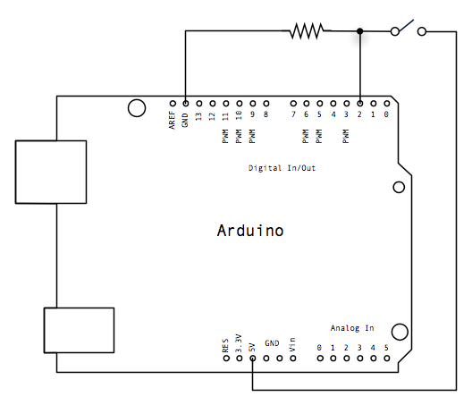
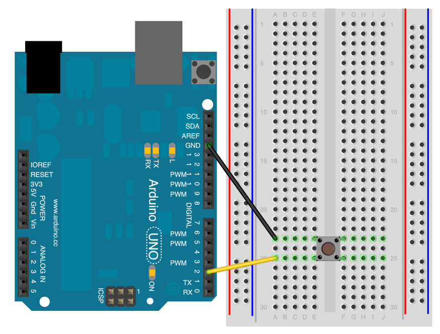
数字输入端、输出端在初始化setup被设置为input模式,out模式。数字输入端和开关相连开关闭合时,直接接到高电平。打开时通过一个接地的电阻和低电平相连(接地的电阻被称为下拉电阻,接5V的被称为上拉电阻),没有这个电阻,高电平和低电平就短路了。由此这个电阻阻值还比较大,以减少电流降低功耗。一般数字输入端要么接高电平,要么接低电平,使用上拉或下拉电阻。
```
// constants won't change. They're used here to set pin numbers:
const int buttonPin = 2; // the number of the pushbutton pin
const int ledPin = 13; // the number of the LED pin
// variables will change:
int buttonState = 0; // variable for reading the pushbutton status
void setup() {
// initialize the LED pin as an output:
pinMode(ledPin, OUTPUT);
// initialize the pushbutton pin as an input:
pinMode(buttonPin, INPUT);
}
void loop() {
// read the state of the pushbutton value:
buttonState = digitalRead(buttonPin);
// check if the pushbutton is pressed. If it is, the buttonState is HIGH:
if (buttonState == HIGH) {
// turn LED on:
digitalWrite(ledPin, HIGH);
} else {
// turn LED off:
digitalWrite(ledPin, LOW);
}
}
```
* [Debounce](https://www.arduino.cc/en/Tutorial/Debounce): 如何读取按键值对噪声进行滤波。

和上面例子接线图一样。但是程序中特别考虑去除键盘抖动。所谓按键抖动,指的时我们按键盘或者开关时,在刚刚状态改变的瞬时(由低到高,或者由高到低),电压状态不稳定,如果恰逢此时我们读取按键值,会得出不准确的结果。我们的一个解决措施是连续几次读取,读取之间的时间间隔大于这个过渡时间。如果读取结果一致就认为我们避开了这个过渡状态。计算机可以很快的读取键盘(毫秒级别),而人类的动作即使很快也是0.1秒的时间间隔。所以不会出现逻辑问题。
```
// constants won't change. They're used here to set pin numbers:
const int buttonPin = 2; // the number of the pushbutton pin
const int ledPin = 13; // the number of the LED pin
// Variables will change:
int ledState = HIGH; // the current state of the output pin
int buttonState; // the current reading from the input pin
int lastButtonState = LOW; // the previous reading from the input pin
// the following variables are unsigned longs because the time, measured in
// milliseconds, will quickly become a bigger number than can be stored in an int.
unsigned long lastDebounceTime = 0; // the last time the output pin was toggled
unsigned long debounceDelay = 50; // the debounce time; increase if the output flickers
void setup() {
pinMode(buttonPin, INPUT);
pinMode(ledPin, OUTPUT);
// set initial LED state
digitalWrite(ledPin, ledState);
}
void loop() {
// read the state of the switch into a local variable:
int reading = digitalRead(buttonPin);
// check to see if you just pressed the button
// (i.e. the input went from LOW to HIGH), and you've waited long enough
// since the last press to ignore any noise:
// If the switch changed, due to noise or pressing:
if (reading != lastButtonState) {
// reset the debouncing timer
lastDebounceTime = millis();
}
if ((millis() - lastDebounceTime) > debounceDelay) {
// whatever the reading is at, it's been there for longer than the debounce
// delay, so take it as the actual current state:
// if the button state has changed:
if (reading != buttonState) {
buttonState = reading;
// only toggle the LED if the new button state is HIGH
if (buttonState == HIGH) {
ledState = !ledState;
}
}
}
// set the LED:
digitalWrite(ledPin, ledState);
// save the reading. Next time through the loop, it'll be the lastButtonState:
lastButtonState = reading;
}
```
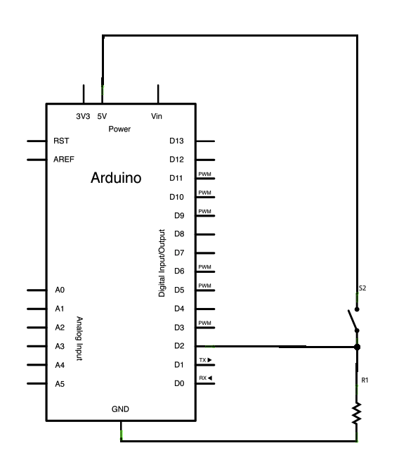
* [Digital Input Pullup](https://www.arduino.cc/en/Tutorial/InputPullupSerial): 展示了使用 INPUT\_PULLUP 模式的 pinMode(设置)。
大家仔细看这个电路图,是不是数字输入接法有点奇怪?当开关闭合时,自然是接低电平,打开以后D2端口处于悬空浮接状态,没有像以前一样和5V相连(通过电阻)。其实,程序中这个数字输入端口被设置为INPUT_PULLUP(输入带上拉,在Arduinio芯片内部),如果设定为此状态,已经将此端口通过20K电阻和5V相连了。所以外面就不需要接上拉电阻了。除此以外这个程序就不需要解释了。
```
void setup() {
//start serial connection
Serial.begin(9600);
//configure pin 2 as an input and enable the internal pull-up resistor
pinMode(2, INPUT_PULLUP);
pinMode(13, OUTPUT);
}
void loop() {
//read the pushbutton value into a variable
int sensorVal = digitalRead(2);
//print out the value of the pushbutton
Serial.println(sensorVal);
// Keep in mind the pull-up means the pushbutton's logic is inverted. It goes
// HIGH when it's open, and LOW when it's pressed. Turn on pin 13 when the
// button's pressed, and off when it's not:
if (sensorVal == HIGH) {
digitalWrite(13, LOW);
} else {
digitalWrite(13, HIGH);
}
}
```
* [State Change Detection](https://www.arduino.cc/en/Tutorial/StateChangeDetection): 计算了按键被按的次数。
这个接线图已经出现过了,不需要解释。
```
// this constant won't change:
const int buttonPin = 2; // the pin that the pushbutton is attached to
const int ledPin = 13; // the pin that the LED is attached to
// Variables will change:
int buttonPushCounter = 0; // counter for the number of button presses
int buttonState = 0; // current state of the button
int lastButtonState = 0; // previous state of the button
void setup() {
// initialize the button pin as a input:
pinMode(buttonPin, INPUT);
// initialize the LED as an output:
pinMode(ledPin, OUTPUT);
// initialize serial communication:
Serial.begin(9600);
}
void loop() {
// read the pushbutton input pin:
buttonState = digitalRead(buttonPin);
// compare the buttonState to its previous state
if (buttonState != lastButtonState) {
// if the state has changed, increment the counter
if (buttonState == HIGH) {
// if the current state is HIGH then the button went from off to on:
buttonPushCounter++;
Serial.println("on");
Serial.print("number of button pushes: ");
Serial.println(buttonPushCounter);
} else {
// if the current state is LOW then the button went from on to off:
Serial.println("off");
}
// Delay a little bit to avoid bouncing
delay(50);
}
// save the current state as the last state, for next time through the loop
lastButtonState = buttonState;
// turns on the LED every four button pushes by checking the modulo of the
// button push counter. the modulo function gives you the remainder of the
// division of two numbers:
if (buttonPushCounter % 4 == 0) {
digitalWrite(ledPin, HIGH);
} else {
digitalWrite(ledPin, LOW);
}
}
```
程序统计了按键被按下的次数,并将键盘当前状态和总的按键次数通过串口发送给PC机。
* [Tone Keyboard](https://www.arduino.cc/en/Tutorial/toneKeyboard): 包含一个三个键的音乐键盘,使用力传感器和晶振扬声器。这个传感器,可以参考[https://butlertechnologies.com/shunt-mode-vs-thru-mode/](https://butlertechnologies.com/shunt-mode-vs-thru-mode/)。类似于一个压力控制的可变电阻,主要使用在电子乐器的按键上。
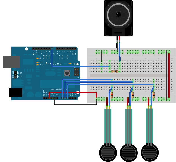
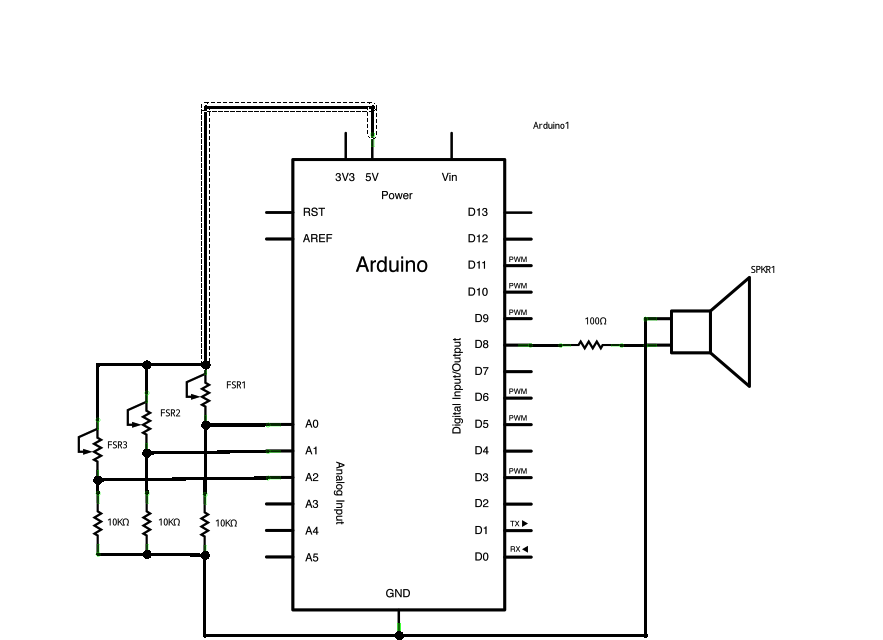
程序在循环中读取三个模拟输入电压值,如果大于一定阈值认为按键被按下,则播放对应的音调即可。播放使用了tone 函数。参考:[https://www.arduino.cc/reference/en/language/functions/advanced-io/tone/](https://www.arduino.cc/reference/en/language/functions/advanced-io/tone/)
```
#include "pitches.h"
const int threshold = 10; // minimum reading of the sensors that generates a note
// notes to play, corresponding to the 3 sensors:
int notes[] = {
NOTE_A4, NOTE_B4, NOTE_C3
};
void setup() {
}
void loop() {
for (int thisSensor = 0; thisSensor < 3; thisSensor++) {
// get a sensor reading:
int sensorReading = analogRead(thisSensor);
// if the sensor is pressed hard enough:
if (sensorReading > threshold) {
// play the note corresponding to this sensor:
tone(8, notes[thisSensor], 20);
}
}
}
```
* [Tone Melody](https://www.arduino.cc/en/Tutorial/toneMelody): 使用晶振扬声器播放旋律.
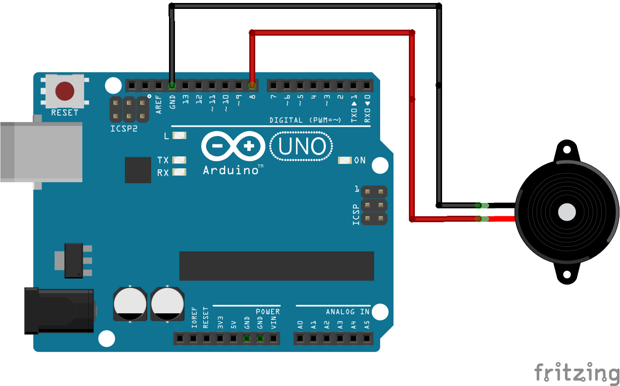
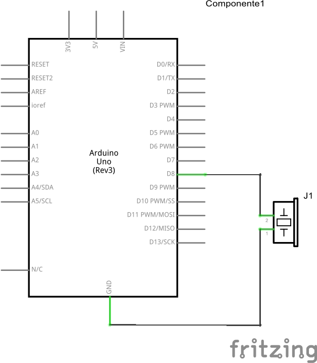
图中的发声器件为蜂鸣器(piezo buzzer),是小巧便宜的发声元器件。
```
#include "pitches.h"
// notes in the melody:
int melody[] = {
NOTE_C4, NOTE_G3, NOTE_G3, NOTE_A3, NOTE_G3, 0, NOTE_B3, NOTE_C4
};
// note durations: 4 = quarter note, 8 = eighth note, etc.:
int noteDurations[] = {
4, 8, 8, 4, 4, 4, 4, 4
};
void setup() {
// iterate over the notes of the melody:
for (int thisNote = 0; thisNote < 8; thisNote++) {
// to calculate the note duration, take one second divided by the note type.
//e.g. quarter note = 1000 / 4, eighth note = 1000/8, etc.
int noteDuration = 1000 / noteDurations[thisNote];
tone(8, melody[thisNote], noteDuration);
// to distinguish the notes, set a minimum time between them.
// the note's duration + 30% seems to work well:
int pauseBetweenNotes = noteDuration * 1.30;
delay(pauseBetweenNotes);
// stop the tone playing:
noTone(8);
}
}
void loop() {
// no need to repeat the melody.
}
```
程序比较简单,主要理解tone的用法之后就好理解了。
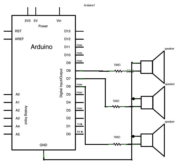
* [Tone Multiple](https://www.arduino.cc/en/Tutorial/toneMultiple): 播放音调在3个扬声器上轮流发声(使用 tone() 命令).

```
void setup() {
}
void loop() {
// turn off tone function for pin 8:
noTone(8);
// play a note on pin 6 for 200 ms:
tone(6, 440, 200);
delay(200);
// turn off tone function for pin 6:
noTone(6);
// play a note on pin 7 for 500 ms:
tone(7, 494, 500);
delay(500);
// turn off tone function for pin 7:
noTone(7);
// play a note on pin 8 for 300 ms:
tone(8, 523, 300);
delay(300);
}
```
程序逻辑也比较简单。
* [Tone Pitch Follower](https://www.arduino.cc/en/Tutorial/tonePitchFollower): 读取一个模拟输入端口,控制发音的声调。
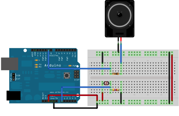
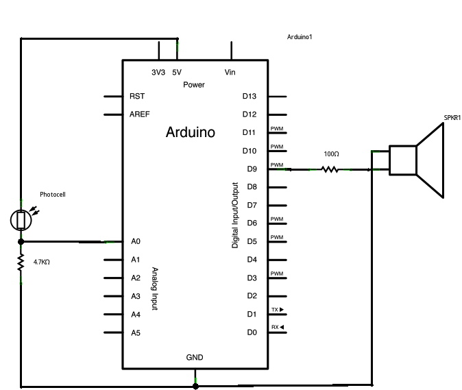
这里使用了photecell,翻译为光电管将光能转换为电能,输入arduino。
```
void setup() {
// initialize serial communications (for debugging only):
Serial.begin(9600);
}
void loop() {
// read the sensor:
int sensorReading = analogRead(A0);
// print the sensor reading so you know its range
Serial.println(sensorReading);
// map the analog input range (in this case, 400 - 1000 from the photoresistor)
// to the output pitch range (120 - 1500Hz)
// change the minimum and maximum input numbers below depending on the range
// your sensor's giving:
int thisPitch = map(sensorReading, 400, 1000, 120, 1500);
// play the pitch:
tone(9, thisPitch, 10);
delay(1); // delay in between reads for stability
}
```
如果改变Arduino光电管的环境光线(通过手电或其它可调光源),则改变了模拟输入电压,则改变了输出音调。
- 序言
- 第一章 arduino简介和学习
- 第一节 arduino介绍
- 第二节 学习方法概述
- 第三节 计算机的智能
- 第二章 开始学习之旅
- 第一节 安装环境和购买硬件的说明
- 第二节 介绍一个具体的范例
- 第三章 分类官网教程讲解
- 第一节 Basics类的示例项目
- 第二节 数字端口的示例
- 第三节 模拟端口的示例
- 第四节 串口通信的示例
- 第五节 LED显示的示例
- 第六节 arduino处理矩阵键盘
- 第七节 LCD显示范例
- 第四章 综合实践项目制作教程
- 第一节 简单的计算器
- 第五章 复习题
- 单选题
- 编程题目
- 单选题答案
- 编程题答案
- 第1题
- 第2题
- 第3题
- 第4题
- 第5题
- 第6题
- 第7题
- 第8题
- 第9题
- 第10题
- 第11题
- 第12题
- 第13题
- 第14题
- 第15题
- 第16题
- 第17题
- 复习题包含翻译
- 第六章 快速复习
- 第一节 英文解说