
* [模拟输入输出串行](https://www.arduino.cc/en/Tutorial/AnalogInOutSerial):读取模拟输入引脚,映射结果,然后使用该数据使LED变暗或变亮。
:-: 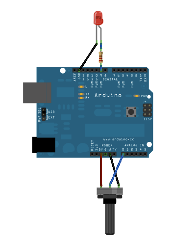
:-: 接线图
:-: 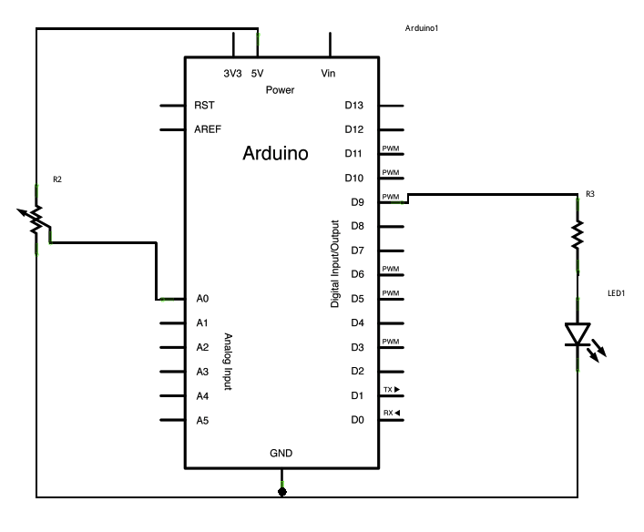
:-: 原理图
```
/*
Analog input, analog output, serial output
Reads an analog input pin, maps the result to a range from 0 to 255 and uses
the result to set the pulse width modulation (PWM) of an output pin.
Also prints the results to the Serial Monitor.
The circuit:
- potentiometer connected to analog pin 0.
Center pin of the potentiometer goes to the analog pin.
side pins of the potentiometer go to +5V and ground
- LED connected from digital pin 9 to ground
created 29 Dec. 2008
modified 9 Apr 2012
by Tom Igoe
This example code is in the public domain.
http://www.arduino.cc/en/Tutorial/AnalogInOutSerial
*/
// These constants won't change. They're used to give names to the pins used:
const int analogInPin = A0; // Analog input pin that the potentiometer is attached to
const int analogOutPin = 9; // Analog output pin that the LED is attached to
int sensorValue = 0; // value read from the pot
int outputValue = 0; // value output to the PWM (analog out)
void setup() {
// initialize serial communications at 9600 bps:
Serial.begin(9600);
}
void loop() {
// read the analog in value:
sensorValue = analogRead(analogInPin);
// map it to the range of the analog out:
outputValue = map(sensorValue, 0, 1023, 0, 255);
// change the analog out value:
analogWrite(analogOutPin, outputValue);
// print the results to the Serial Monitor:
Serial.print("sensor = ");
Serial.print(sensorValue);
Serial.print("\t output = ");
Serial.println(outputValue);
// wait 2 milliseconds before the next loop for the analog-to-digital
// converter to settle after the last reading:
delay(2);
}
```
本示例说明如何读取模拟输入引脚,如何将结果由内部 A/D变换到0到255的数字范围,如何使用该结果设置输出引脚的脉冲宽度调制(PWM)以使LED变暗或变亮以及将值打印在Arduino软件(IDE)的串行监视器。 电位器的模拟输入和内部的A/D已经在第二章进行了介绍,PWM在第一节介绍过了,不再解释。这里我们介绍一下传感器应用中经常使用的函数[map](https://www.arduino.cc/reference/en/language/functions/math/map/),而map函数的实际代码为:
```
long map(long x, long in_min, long in_max, long out_min, long out_max)
{
return (x - in_min) * (out_max - out_min) / (in_max - in_min) + out_min;
}
```
map函数实现了一个数学上的线性映射,就是将一段输入范围的值映射到另外一个范围。所谓线性映射就是乘以一个统一的系数,也可以为正,也可以为负数。传感器一般是将某种测量物理量线性映射到某个区间的电信号(电压,电流,等)。传感器的放大电路一般将信号尽可能放大到A/D变换对应的量程,对于arduino来说就是0~5V,对应的数字量就是0~255。我们可以用map函数将测量结果再次映射到对应的物理量范围,比如0~80摄氏度,0~500牛,0~100帕等等。这样我们就得到了对应的物理测量结果。
* [模拟输入](https://www.arduino.cc/en/Tutorial/AnalogInput):使用电位计控制LED的闪烁。
:-: 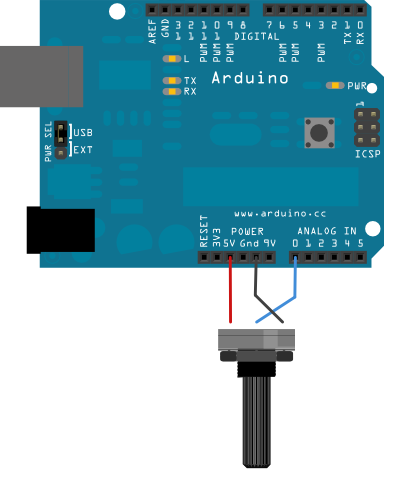
:-: 接线图
:-: 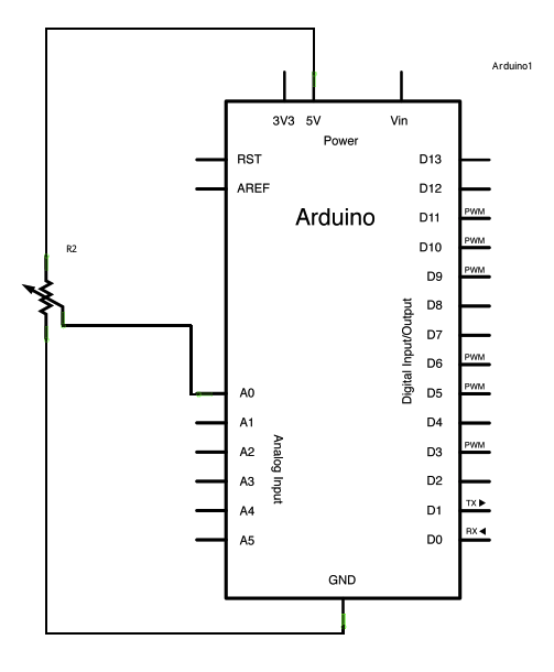
:-: 原理图
```
/*
Analog Input
Demonstrates analog input by reading an analog sensor on analog pin 0 and
turning on and off a light emitting diode(LED) connected to digital pin 13.
The amount of time the LED will be on and off depends on the value obtained
by analogRead().
The circuit:
- potentiometer
center pin of the potentiometer to the analog input 0
one side pin (either one) to ground
the other side pin to +5V
- LED
anode (long leg) attached to digital output 13
cathode (short leg) attached to ground
- Note: because most Arduinos have a built-in LED attached to pin 13 on the
board, the LED is optional.
created by David Cuartielles
modified 30 Aug 2011
By Tom Igoe
This example code is in the public domain.
http://www.arduino.cc/en/Tutorial/AnalogInput
*/
int sensorPin = A0; // select the input pin for the potentiometer
int ledPin = 13; // select the pin for the LED
int sensorValue = 0; // variable to store the value coming from the sensor
void setup() {
// declare the ledPin as an OUTPUT:
pinMode(ledPin, OUTPUT);
}
void loop() {
// read the value from the sensor:
sensorValue = analogRead(sensorPin);
// turn the ledPin on
digitalWrite(ledPin, HIGH);
// stop the program for <sensorValue> milliseconds:
delay(sensorValue);
// turn the ledPin off:
digitalWrite(ledPin, LOW);
// stop the program for for <sensorValue> milliseconds:
delay(sensorValue);
}
```
这个程序没有使用PWM功能 ,而是简单的延时。延时的时长等于模拟输入的值。因此当阻值很大时可以看出灯的亮灭,很小时则看不出来了。
* [Analog Write Mega](https://www.arduino.cc/en/Tutorial/AnalogWriteMega):使用Arduino Mega板一个接一个地淡化12个LED。
:-: 
:-: 接线图
:-: 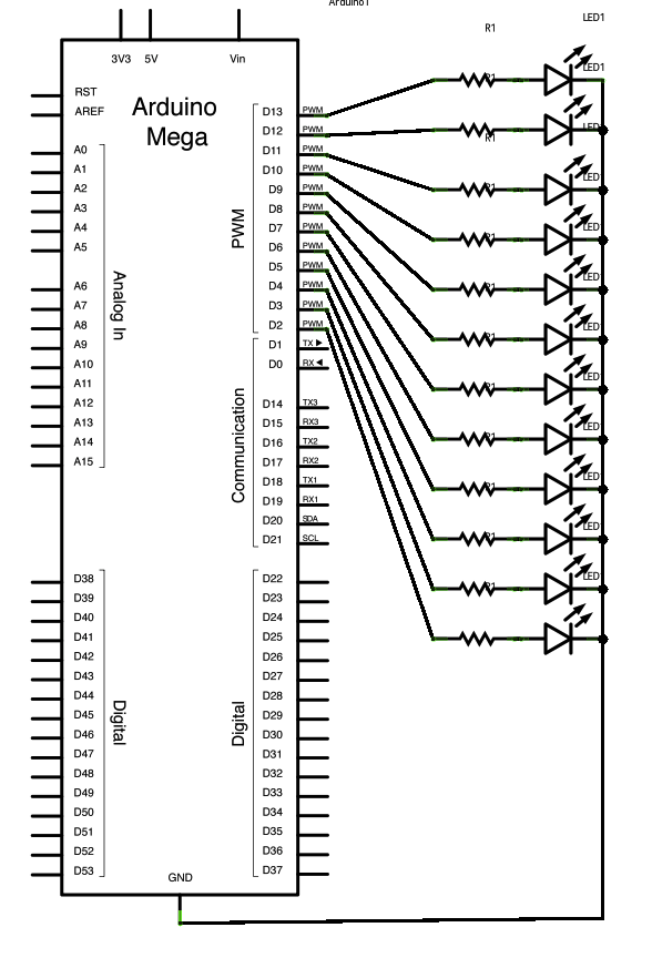
:-: 原理图
```
/*
Mega analogWrite() test
This sketch fades LEDs up and down one at a time on digital pins 2 through 13.
This sketch was written for the Arduino Mega, and will not work on other boards.
The circuit:
- LEDs attached from pins 2 through 13 to ground.
created 8 Feb 2009
by Tom Igoe
This example code is in the public domain.
http://www.arduino.cc/en/Tutorial/AnalogWriteMega
\*/
// These constants won't change. They're used to give names to the pins used:
constintlowestPin\=2;
constinthighestPin\=13;
voidsetup(){
// set pins 2 through 13 as outputs:
for(intthisPin\=lowestPin;thisPin<=highestPin;thisPin++){
pinMode(thisPin,OUTPUT);
}
}
voidloop(){
// iterate over the pins:
for(intthisPin=lowestPin;thisPin<=highestPin;thisPin++){
// fade the LED on thisPin from off to brightest:
for(intbrightness=0;brightness<255;brightness++){
analogWrite(thisPin,brightness);
delay(2);
}
// fade the LED on thisPin from brightest to off:
for(intbrightness=255;brightness>=0;brightness--){
analogWrite(thisPin,brightness);
delay(2);
}
// pause between LEDs:
delay(100);
}
}
```
这个例子主要针对mega开发板,不再介绍。
* [校准](https://www.arduino.cc/en/Tutorial/Calibration):定义模拟传感器预期值的最大值和最小值。本示例演示了一种用于校准传感器输入的技术。该板在启动期间会读取传感器的读数五秒钟,并跟踪其获得的最高和最低值。在草图执行的前五秒内,这些传感器读数定义了循环期间获取的读数的期望值的最小值和最大值。
:-: 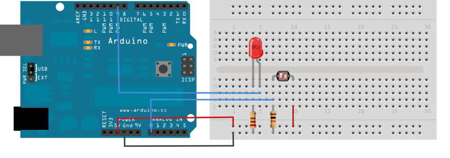
:-: 接线图
用串联的220欧姆限流电阻将LED连接到数字引脚9。将光敏电阻连接到5V,然后通过10K欧姆电阻将其连接到模拟引脚0。
:-: 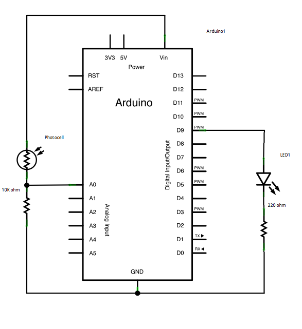
:-: 原理图
```
/*
Calibration
Demonstrates one technique for calibrating sensor input. The sensor readings
during the first five seconds of the sketch execution define the minimum and
maximum of expected values attached to the sensor pin.
The sensor minimum and maximum initial values may seem backwards. Initially,
you set the minimum high and listen for anything lower, saving it as the new
minimum. Likewise, you set the maximum low and listen for anything higher as
the new maximum.
The circuit:
- analog sensor (potentiometer will do) attached to analog input 0
- LED attached from digital pin 9 to ground
created 29 Oct 2008
by David A Mellis
modified 30 Aug 2011
by Tom Igoe
This example code is in the public domain.
http://www.arduino.cc/en/Tutorial/Calibration
*/
// These constants won't change:
const int sensorPin = A0; // pin that the sensor is attached to
const int ledPin = 9; // pin that the LED is attached to
// variables:
int sensorValue = 0; // the sensor value
int sensorMin = 1023; // minimum sensor value
int sensorMax = 0; // maximum sensor value
void setup() {
// turn on LED to signal the start of the calibration period:
pinMode(13, OUTPUT);
digitalWrite(13, HIGH);
// calibrate during the first five seconds
while (millis() < 5000) {
sensorValue = analogRead(sensorPin);
// record the maximum sensor value
if (sensorValue > sensorMax) {
sensorMax = sensorValue;
}
// record the minimum sensor value
if (sensorValue < sensorMin) {
sensorMin = sensorValue;
}
}
// signal the end of the calibration period
digitalWrite(13, LOW);
}
void loop() {
// read the sensor:
sensorValue = analogRead(sensorPin);
// apply the calibration to the sensor reading
sensorValue = map(sensorValue, sensorMin, sensorMax, 0, 255);
// in case the sensor value is outside the range seen during calibration
sensorValue = constrain(sensorValue, 0, 255);
// fade the LED using the calibrated value:
analogWrite(ledPin, sensorValue);
}
```
主要介绍了传感器使用的函数[map](https://www.arduino.cc/reference/en/language/functions/math/map/),而map函数已经介绍过了。
```
long map(long x, long in_min, long in_max, long out_min, long out_max)
{
return (x - in_min) * (out_max - out_min) / (in_max - in_min) + out_min;
}
```
* [淡入淡出](https://www.arduino.cc/en/Tutorial/Fading):使用模拟输出(PWM引脚)使LED淡入淡出。
:-: 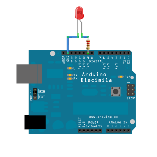
:-: 接线图
:-: 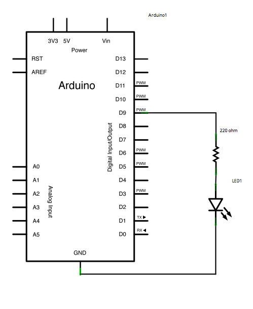
:-: 原理图
```
/*
Fade
This example shows how to fade an LED on pin 9 using the analogWrite()
function.
The analogWrite() function uses PWM, so if you want to change the pin you're
using, be sure to use another PWM capable pin. On most Arduino, the PWM pins
are identified with a "~" sign, like ~3, ~5, ~6, ~9, ~10 and ~11.
This example code is in the public domain.
http://www.arduino.cc/en/Tutorial/Fade
*/
int led = 9; // the PWM pin the LED is attached to
int brightness = 0; // how bright the LED is
int fadeAmount = 5; // how many points to fade the LED by
// the setup routine runs once when you press reset:
void setup() {
// declare pin 9 to be an output:
pinMode(led, OUTPUT);
}
// the loop routine runs over and over again forever:
void loop() {
// set the brightness of pin 9:
analogWrite(led, brightness);
// change the brightness for next time through the loop:
brightness = brightness + fadeAmount;
// reverse the direction of the fading at the ends of the fade:
if (brightness <= 0 || brightness >= 255) {
fadeAmount = -fadeAmount;
}
// wait for 30 milliseconds to see the dimming effect
delay(30);
}
```
这个例子在第一节已经介绍过了。
* [平滑](https://www.arduino.cc/en/Tutorial/Smoothing):平滑模拟输入的多个读数。该示例从模拟输入中重复读取,计算出运行平均值并将其打印到计算机上。该示例对于消除跳动或不稳定传感器的值很有用,并且还演示了使用[数组](https://www.arduino.cc/en/Reference/Array)存储数据的方法。
:-: 
:-: 接线图
:-: 
:-: 原理图
```
/*
Smoothing
Reads repeatedly from an analog input, calculating a running average and
printing it to the computer. Keeps ten readings in an array and continually
averages them.
The circuit:
- analog sensor (potentiometer will do) attached to analog input 0
created 22 Apr 2007
by David A. Mellis <dam@mellis.org>
modified 9 Apr 2012
by Tom Igoe
This example code is in the public domain.
http://www.arduino.cc/en/Tutorial/Smoothing
*/
// Define the number of samples to keep track of. The higher the number, the
// more the readings will be smoothed, but the slower the output will respond to
// the input. Using a constant rather than a normal variable lets us use this
// value to determine the size of the readings array.
const int numReadings = 10;
int readings[numReadings]; // the readings from the analog input
int readIndex = 0; // the index of the current reading
int total = 0; // the running total
int average = 0; // the average
int inputPin = A0;
void setup() {
// initialize serial communication with computer:
Serial.begin(9600);
// initialize all the readings to 0:
for (int thisReading = 0; thisReading < numReadings; thisReading++) {
readings[thisReading] = 0;
}
}
void loop() {
// subtract the last reading:
total = total - readings[readIndex];
// read from the sensor:
readings[readIndex] = analogRead(inputPin);
// add the reading to the total:
total = total + readings[readIndex];
// advance to the next position in the array:
readIndex = readIndex + 1;
// if we're at the end of the array...
if (readIndex >= numReadings) {
// ...wrap around to the beginning:
readIndex = 0;
}
// calculate the average:
average = total / numReadings;
// send it to the computer as ASCII digits
Serial.println(average);
delay(1); // delay in between reads for stability
}
```
解释了如何通过最基本的滤波克服噪声或者其它影响,提高传感器测量精度。这里的滤波算法就是10个测量值取平均,假如某个时刻一个测量结果受到干扰产生误差为e,则经过平均以后误差为e/10。如果对干扰的特性有所了解则可以使用更加复杂的滤波算法。
- 序言
- 第一章 arduino简介和学习
- 第一节 arduino介绍
- 第二节 学习方法概述
- 第三节 计算机的智能
- 第二章 开始学习之旅
- 第一节 安装环境和购买硬件的说明
- 第二节 介绍一个具体的范例
- 第三章 分类官网教程讲解
- 第一节 Basics类的示例项目
- 第二节 数字端口的示例
- 第三节 模拟端口的示例
- 第四节 串口通信的示例
- 第五节 LED显示的示例
- 第六节 arduino处理矩阵键盘
- 第七节 LCD显示范例
- 第四章 综合实践项目制作教程
- 第一节 简单的计算器
- 第五章 复习题
- 单选题
- 编程题目
- 单选题答案
- 编程题答案
- 第1题
- 第2题
- 第3题
- 第4题
- 第5题
- 第6题
- 第7题
- 第8题
- 第9题
- 第10题
- 第11题
- 第12题
- 第13题
- 第14题
- 第15题
- 第16题
- 第17题
- 复习题包含翻译
- 第六章 快速复习
- 第一节 英文解说